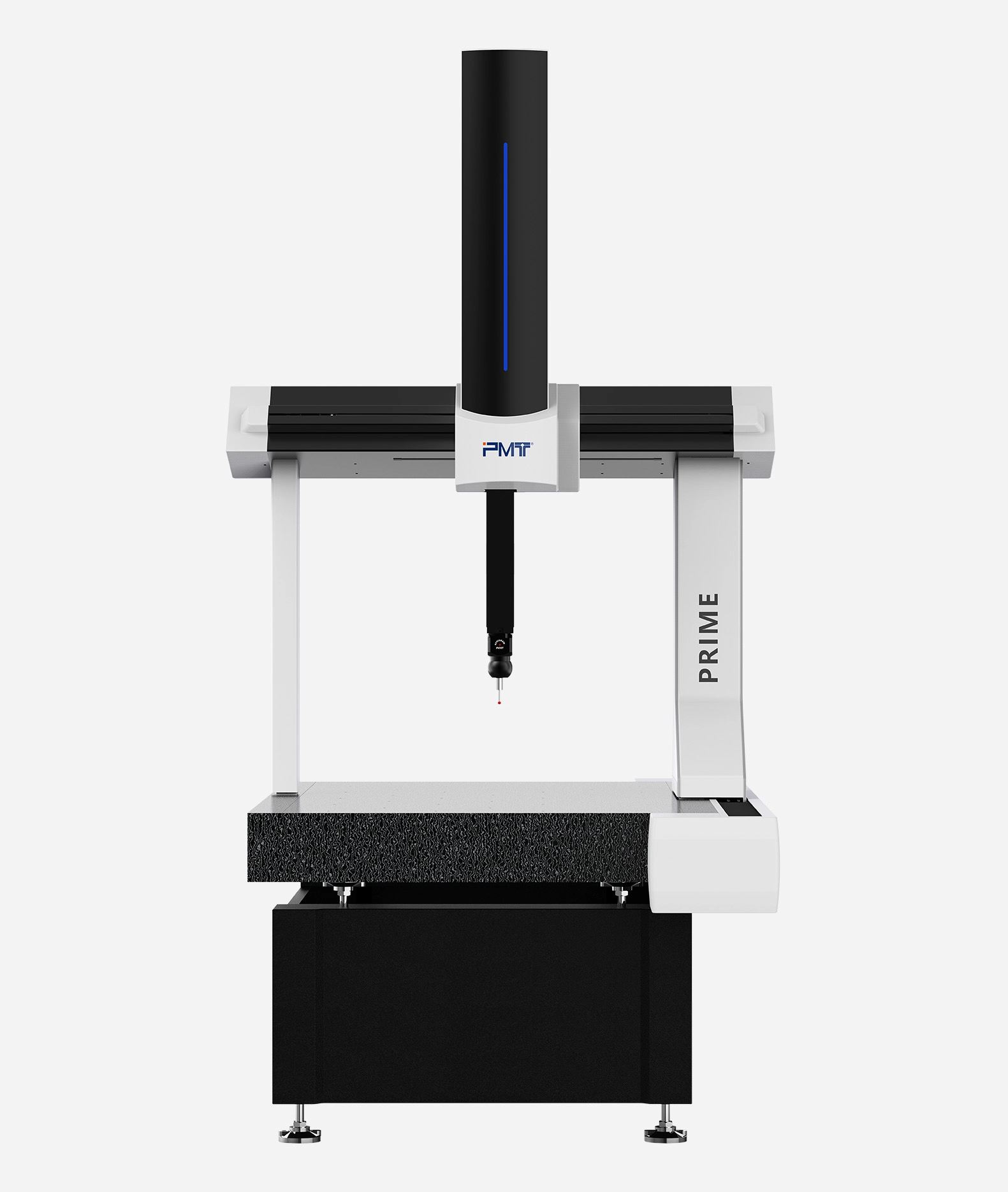
A bridge CMM diagram gives engineers and purchasing teams a visual explanation of how a coordinate measuring machine is built and how its structural elements support measurement accuracy. Rather than showing only the machine’s external appearance, the diagram can reveal the relationship between the bridge, guideways, measuring axes, drive system, worktable, and probe. For business buyers, understanding these details helps connect machine architecture with inspection stability, repeatability, maintenance, and suitability for demanding production environments.
What Does a Bridge CMM Diagram Typically Show?
A bridge CMM uses a bridge structure to position a measuring probe over a workpiece. The machine establishes three-dimensional measurement through coordinated X, Y, and Z axis movements, allowing the probe to collect spatial points from the component. These points can then be processed to evaluate dimensions and geometric deviations.
A typical bridge CMM diagram therefore identifies the structural frame, base or table, axis guideways, drive mechanisms, measuring scales, and probing system. The exact configuration differs among manufacturers, but the purpose is similar: to show how mechanical stability and controlled movement support accurate coordinate measurement.
For procurement teams, the diagram is more than an engineering illustration. It can help explain why two machines with similar measuring ranges may deliver different levels of stability and repeatability.
The Bridge and Beam Are Central to Machine Stability
The bridge is one of the most important elements shown in a bridge CMM diagram because it supports the moving measurement system. Its geometry affects stiffness, thermal behavior, and resistance to deformation during axis movement.
PMT’s PRIME Bridge CMM uses an equilateral triangle beam structure. According to PMT, this aluminum-alloy beam geometry provides thermal balance and isotropic characteristics, helping maintain consistent structural behavior in different directions. This design is intended to support stable measurement performance across the working envelope.
For production users, structural consistency matters because inspection results should remain dependable when measurements move from one location on a component to another.
How the Base Supports the Bridge CMM Structure
The base or worktable is another key area shown in a bridge CMM diagram. It provides the foundation for the workpiece and the machine’s guide system, so its rigidity and thermal characteristics can directly influence the measurement environment.
The PRIME Bridge CMM uses a natural granite base. PMT describes granite as offering high rigidity and thermal stability, helping resist deformation. Granite is also widely used in precision metrology structures because dimensional stability is important when measurement tolerances become increasingly small.
A stable foundation gives the bridge and moving axes a more consistent reference. This is particularly relevant for automotive, aerospace, precision manufacturing, and metrology applications where dimensional inspection forms part of formal quality-control processes.
Guideways, Scales, and Drive Systems in a Bridge CMM Diagram
A detailed bridge CMM diagram may also identify the guideways and transmission components that control movement along the measurement axes. These elements determine how smoothly and accurately the probe reaches its intended coordinates.
PMT states that its CMM technology combines an advanced photoelectric incremental grating scale with a precision transmission mechanism. The combination is designed to support micron-level measurement accuracy as well as stable and repeatable measurement results.
The drive mechanism is equally important. The PRIME uses a flexible synchronous belt containing built-in steel wire. PMT explains that this design combines flexible meshing with rigid axial transmission, helping reduce vibration and jitter during movement while supporting high-precision positioning.
Why Beam Geometry Matters for Business Buyers
A bridge CMM diagram allows engineering and quality teams to examine machine architecture before focusing only on headline accuracy specifications. Beam geometry, support structure, transmission method, and measurement scales all contribute to how a CMM behaves during inspection.
This is especially important when a CMM will be integrated into regular production quality control. A machine may perform differently when used repeatedly throughout a shift than when operated only for occasional laboratory inspection. Structural stability, repeatability, and resistance to environmental influences therefore deserve attention during equipment selection.
PMT positions its CMM portfolio for production sites, R&D centers, and metrology laboratories. Its CMM range includes the FUTURE, PRIME, SPACE, and LOONG series, covering different measurement environments and workpiece requirements.
Reading the PRIME Bridge CMM Structure as a Complete System
The PRIME should not be evaluated by looking at its beam alone. Its structure is designed as an interconnected system in which the granite base, equilateral triangle beam, transmission mechanism, and photoelectric incremental grating scale work together.
This system-level perspective is useful when comparing CMM solutions for professional inspection. The beam provides structural support, the base establishes a stable reference, the drive system controls movement, and the grating scale provides position feedback for measurement.
PMT also provides different CMM series for different applications. Its official product portfolio includes bridge CMMs, shop-floor CMMs, and gantry CMMs, while the wider product range includes portable measuring arms, handheld 3D scanners, measurement software, measuring accessories, and high-accuracy encoders.
Turning a Bridge CMM Diagram into a Purchasing Tool
For business buyers, the most useful approach is to treat a bridge CMM diagram as the starting point for technical evaluation. The diagram can help identify which structural elements require closer review, followed by verification of measuring range, accuracy, environmental requirements, probe options, software compatibility, and available support.
This approach also helps purchasing teams communicate more effectively with engineering departments. Instead of comparing machines only by price or advertised accuracy, buyers can evaluate whether the machine structure matches the company’s actual inspection workload and quality requirements.
Understanding Structure Before Choosing a CMM
A bridge CMM diagram provides a practical window into the engineering logic behind coordinate measurement equipment. It shows how the bridge, beam, base, guideways, transmission components, and measurement system are arranged to create a controlled three-dimensional inspection platform.
PMT‘s PRIME Bridge CMM illustrates this principle through its granite base, equilateral triangle beam, photoelectric incremental grating scale, and flexible synchronous belt drive. For manufacturers evaluating precision inspection equipment, studying these structural relationships can provide a stronger technical foundation for selecting a CMM that supports stable and repeatable quality-control operations.
